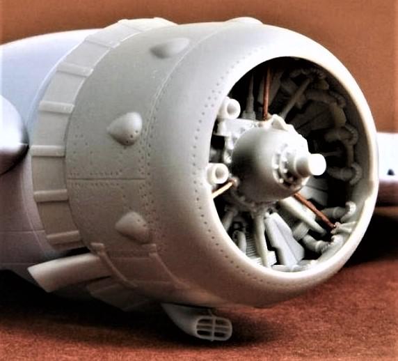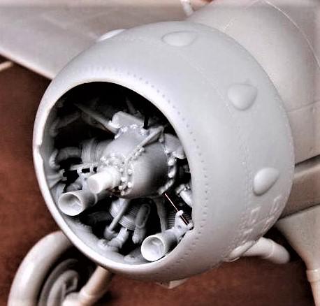
or 2. the cheaper SBS Model Gloster Gladiator Mk I/II Engine and Cowling Set.

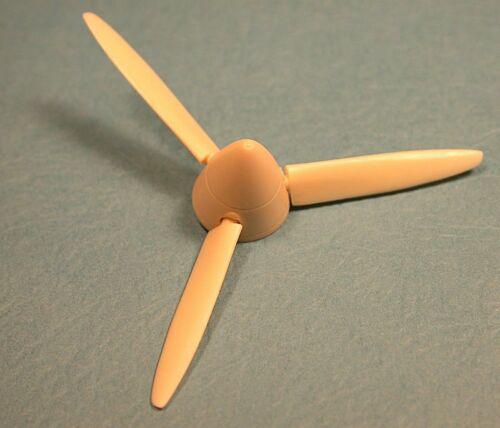
Step 10. For the propeller and spinner, it is suggested that the 1-48 Ultracast 48115 Spitfire Mk V Rotol Propeller and Spinner, available from Red Roo Models, is readily adaptable to suit the scratchbuild.

Step 11. New horizontal tail surfaces can be shaped from thick plastic card or laminated plastic card, with suitably scribed elevators.
Step 12. New floats can be made from the exiting Walrus floats but shaped to match the Sea Otter drawing.
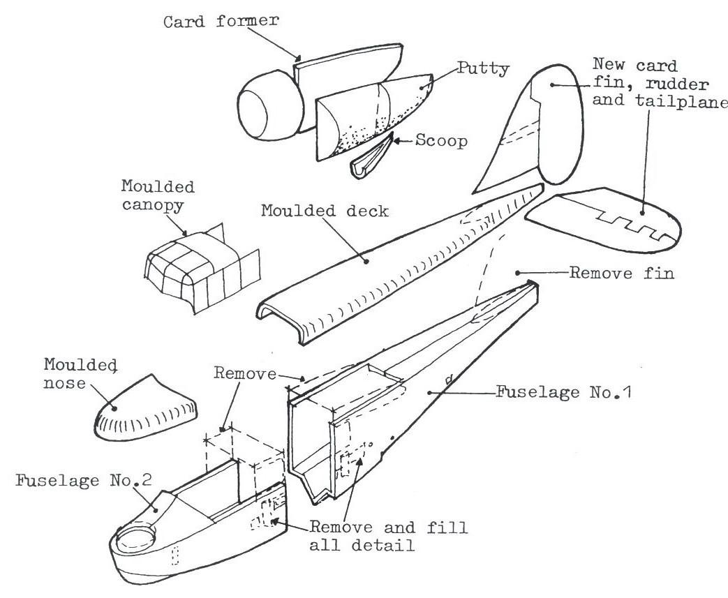
Step 13. A new canopy will need to be moulded to match the drawing.
Step 14. Detailing is up to the individual modeller, depending on the level of accuracy and detail one wants to include, for example, cockpit detail, side rails, two portholes and the starboard side and the single, landing light (two ribs wide, 18 to 20 ribs outboard from the fuselage on the lower port wing. (Note 2)
Step 15. Painting and decaling depending on the subject chosen, either a RAN example or an Australian Petroleum Corporation example. For the RAN examples, generic roundels and lettering will suffice for the national insignia and serial but the Red warning placard and lettering will need to be custom-made unless a generic sign and stripes can be sourced. The civilian examples will need custom-made registration and logo decals unless a generic set can be adapted for the purpose.

Modelling Notes:
1. The wings and horizontal tail surfaces were all-metal with fabric covering. All four wings had ailerons with flaps on the upper wing section. To facilitate the aft wing folding alongside the fuselage, flap sized movable panels on the lower wing and small triangular panels on the upper wing folded to provide appropriate clearance. Check references and drawings.
2. The pilot and navigator both sat on the port side. Grab rails around the lower fuselage on both the port and starboard sides were usually installed in military service. On camouflaged Sea Otters, these were painted Yellow in recognition of the aircraft's air-sea rescue role.
3. There were four catapult spools, two on each side of the lower fuselage; refer to the plans for their placement.
Use the index button to return to the main issue 36/4 index.
